|
heat control
r71
|
|
heat control
r71
|
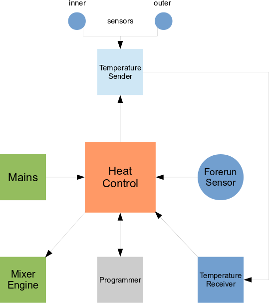
Three channels for NTC thermistors with constant current sources are available for inner and outer temperature measurement and to operate a mixer motor by the comparison result. The mixer motor has two AC 230V coils, one for rotating clockwise (closing the valve - mix less warm water), one for rotating counter clockwise (opening the valve - mix more warm water). These two coils are operated by two controller outputs each driving a solid state relay with zero crossing detection.
By comparing a nominal inner (room) temperature, adjusted through two buttons and an alphanumeric liquid crystal display, against the actual inner and outer temperature values, the inner temperature slightly should follow the nominal one. The two channels for temperature measurement are planned for measuring the inner and outer temperature. A well designed algorithm has to be developed to be able to control the actual inner temperature in conjunction with the values:
This newly designed control is for replacement of an old original one, which has serious defects, so no automatism is possible any longer. Procedures of temperature changes are very slow as seen life on the old control. The goal is to gentle rise and lower the heating circuit, not to stress the material by following the nominal values as fast as possible.
The heart is an Atmel ATtiny861 CPU running @ 8MHz for
Inner and outer temperatures are coming from the remote RF-temperature sender, located in the 1st floor, the forerun temperature is acquired locally at heat control, basement located, wich just supplies the sender with DC 6V power and itself is powered directly with AC 230V~ mains.
A programmer interface provides firmware and data flashing including updates if there is sufficient memory. The whole system consumpts about 2.5 Watts continuously.
hc time based schedules controlling cycles dependent on IV_MEAS, which has a value of '5 minutes' as a factory default and is not user configurable this time.
hc has 2 main controlling mechanisms:
On factory default the learning mode is active, as long as there aren't 70 learning values stored in the eeprom. A learning value is recorded on any user configurable HCI interval and consists of the pair:
whereas the outer temperature is the key value to control the forerun. These two sub-values together form up the so called heating curve at the end. It will take a long time until all 70 pairs of learning values are collected together since it strongly depends on the different weather and climate phases over a year or so.
The most practical method to obtain a working and reliable heating curve is to record some values when it is very cold outside and some when it is very warm, right before the system is shutting down because of a warm enough outer temperature.
When there are a few top and bottom values available, the eeprom can be read out and the values can be converted to import into a data base. Then manual or automatic interpolation can be applied to the data set. Afterwards the data set can be converted back to binary eeprom data and then be flashed back to the controller.
For the controller up- and down loading, a programmer is required like "Diamex All AVR". For data conversion (bin to txt and back) and data interpolation, there is a factory perl tool provided which is called "eeppatch.pl", see also here.
Another way could be to try and error tune the curve step by step, whenever a misconfiguration is identified. But this way costs a lot of time and patience. So the way of interpolation is encouraged.
If you don't care about all of that, you are still not doing wrong. hc automatically switches to "normal operation" when it detects 70 learning values in its eeprom. But it cannot be guaranteed when this will happen. It can take years as mentioned earlier.
The "normal operation" mode is not mandatory, but will lead to more reliable controlling results since the forerun is not that easy manipulated as the inner temperature.
Once all 70 learning values are acquired, you are doing good to make a backup of the whole eeprom with a suitable programmer tool, mentioned above.
| temperature | min [°C] | max [°C] |
|---|---|---|
| inner | 11.3 | 32.5 |
| outer | -20.0 | 32.5 |
| forerun | 16.0 | 65.5 |
| significant change | 0.2 | |
These ranges denote the minimum and maximum processable limits of the three different temperatures being involved in the system. Since the outer temperature sensor is located 7cm in the wall from the outside, the minimum value most likely will be not much below zero '0' degrees of Celsius. A significant temperature change of any value is 0.2°C. This delta threshold is chosen to reach a good balance between erroneous measurement (noise) and real little changes. When exceeded the system comes in action.
| name | unit | (factory) default |
|---|---|---|
| NIT | [°C] | NOM_IN_TMP |
| OIT | [°C] | OFF_IN_TEMP |
| SDT | [°C] | OUT_TMP_SHDN_TH |
| SDD | [min] | SHTDN_DUR |
| ECD | [1/10s] | ENG_CTRL_DUR |
| HCI | hci * IV_MEAS [min] | IV_HCREC |
| TRD | trd * IV_MEAS [min] | OUT_TMP_RISE_DUR |
| TDM | tdm * DELTA_TEMP [°C ] | OUT_TMP_DEL_MULT |
These configurable parameters are for tuning and adjustment of the hc system's behaviour.
Some words to the parameters HCI, TRD and TDM. These parameters are only regarding to the learning mode, which is active by factory default.
Configures the interval on which a learning value shall be taken to store into EEPROM. The configured value is the time which has to be elapsed without a significant inner temperature change. In other words the system must stay "in ballance" for the time configured by HCI before a learning value is recorded. This ensures stable states and suppresses external temperature manipulations.
The value of HCI must be a multiple of the measurement interval IV_MEAS, because only on a controlling cycle the recording of a learning value is possible due to evaluation.
Adjusts the duration of time in which the outer temperature must rise before a control down cycle takes place. When the inner temperature rises, then there can be two main reasons:
To evaluate the distinction of these two cases, the system requires configuration of the outer temperature rising duration. It is a parameter that describes the house's heat insulation value and most likely must be adjusted meore than once.
This is the complement (y-value) of the TRD parameter and together with this forms the heat insulation characteristic following a mathematical straight line function. It's value is the multiple of a standard significant temperature change (0.2°C) and also most likely requires careful maintenance.
The following graph illustrates the house's default insulation straight line:
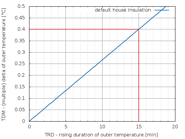
The system's default configuration is denoted by the red markers. Note that these defaults are not approved. It's up to you to tune them during live operation.
By adjusting TRD and TDM you change the gradient of the straight line. Note that you can only tune TRD in multiples of IV_MEAS. Having the ability of tuning also TDM by a multiple of DELTA_TEMP you can accomplish accurate system fine tuning.
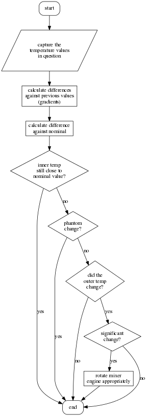
The principal logic shown in the graph runs any few micro seconds and actions are taken every IV_MEAS minutes based on evaluation.
 1.8.6
1.8.6 
