|
heat control
r71
|
|
heat control
r71
|
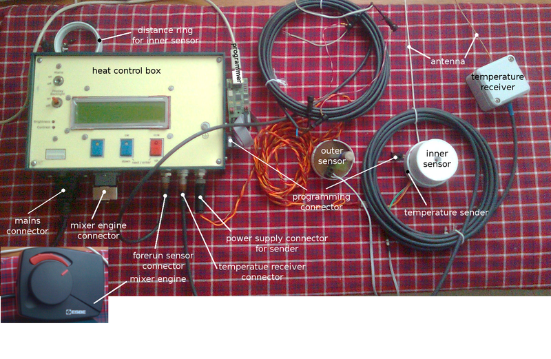
The picture shows all components being involved to properly operate hc. They need to be installed on their designated places. Each component is described in detail by the following sections. Naming is kept as given in the picture.
It is recommended to use the factory connector cables, which come with the system. They have 5 meters in length. Otherwise it isn't guaranteed that everything operates normally.
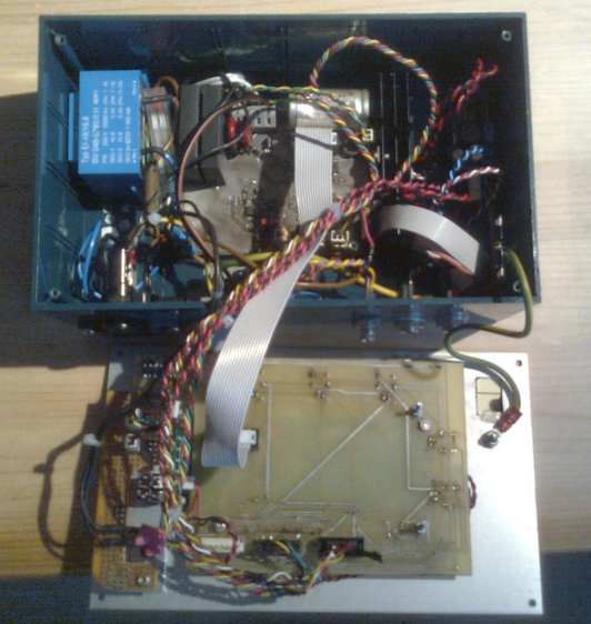
The box, where the whole logic in the form of firmware and electronic is put in, see also. You unmount the front panel to get access to the holes for mounting on a wall, see image. The box usually sits in the basement, where the distance to the forerun sensor is as short as possible (<= 5m).
| technical data | |
|---|---|
| data | value |
| mains | AC 230V~ |
| power consumption [W] | 2.8 |
| temperature ranges [°C] | see description |
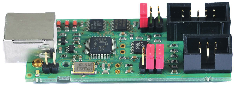
Receives the inner and outer temperature from the corresponding sender and transfers the data to the hc box. This time the data is sent continuously @ 1200 Baud. The RF is between 433.82 MHz and 434.02 MHz and might disturb other devices, like weather stations, communicating on the same frequency channel. So there are plans to turn the data transmission into intervals of 10s in length every 2 or 3 minutes.
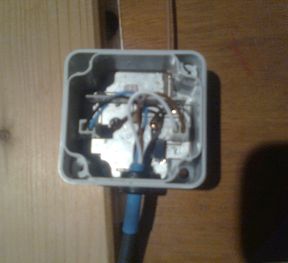
Unscrew the lid to get access to the mounting holes, see picture. The receiver is usually mounted so, that it has good reception to the sender and it 's not far away from the hc box. You can quickly see its proper operation, when you encounter the values (O, I) on the hc box's display, see menue No. 3. close to the hc box.
| technical data | |
|---|---|
| data | value |
| supply voltage [V] | DC 5 |
| power consumption [W] | 40m |
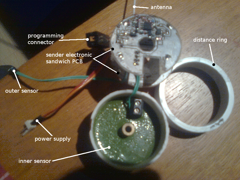
The sender sends the inner and outer temperature (I, O) to the receiver. It is powered directly from within the hc box by 6V DC. See receiver for RF specification. There are connector cables to the outer sensor (green, polarity doesn't matter) and the power supply (red/orange). A distance ring is required for mounting onto a wall. It enables the housing of the sender's sandwich PCB inside the inner sensor chassis. A programming connector is provided (on the fly), so there are firmware updates possible in case of a deeper reconfiguration.
See setup OIT for operation configuration hints. The picture illustrates a disassembly. The collective is mounted on the place, where the inner and outer temperature can be acquired at their best. This should be the original position of the "good old days".
| technical data | |
|---|---|
| data | value |
| supply voltage [V] | DC 6 |
| power consumption [W] | 200m |
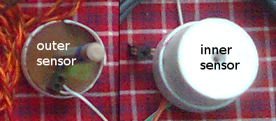
Both sensors are the original ones from the "good old days". The inner sensor provides the housing for the sender electronic, see sender. Since the position of the outer sensor is around 10cm inside the wall, we most likely do not get the real outer temperature and the system must be configured to this by the user as described here and there.
| technical data | |
|---|---|
| data | value |
| R25 | inner RR_IN and outer RR_OUT sensor |
Keep your original sensor and adjust the resistance value @ 25°C properly. No picture available this time.
This programmer is a universal tool for flashing ATMEL AVR micro controllers. A specification can be found here: Diamex All AVR. It's not part of the equipment from the vendor. You can obtain it @ Reichelt Elektronik.
This is just a recommendation. One can use any programmer which fits the needs. It should be able to program the flash and the eeprom of ATtiny861A (the one in the hc box) and ATtiny85L (the one in the temperature sender) controllers.
Using avrdude gives many options to work with binary data to and from the desired controller. The vendor's tool eeppatch provides all tasks to get a working heating curve programmed to the controller. A brief usage documentation is printed out when you call the tool: "perl eeppatch.pl help".
To get an overview about all tools and requirements, see here.
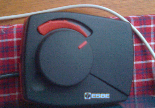
This device takes care of the valve adjustment of the heating circuit. It's not part of the equipment from the vendor. Find a detailed description: ESBE ARA 600. You can purchase it @ Binder Fachhandel für Haustechnik .
 1.8.6
1.8.6 
