|
heat control
r71
|
|
heat control
r71
|
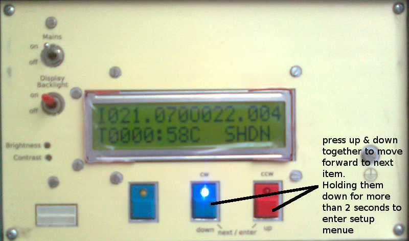
You navigate through the different menues, by pressing the up and down buttons simultaneously. Selecting the different menue items of the setup menue is done by these buttons either. See image above. There is only one forward direction you can navigate through and change values. They start from the beginning if once they are overflowing
In the following paragraphs, all available menues the hc system provide are visualized by pictures. Values

When powering on mains, hc starts with a welcome message, telling you the name of the product, the vendor and the revision of the firmware 'Rxx'. After a few moments it automatically switches to controlling operation -> default immediate menue No. 3. The entered mode depends on the availability of a valid heating curve -> 'FOR', otherwise the learning mode is active.


After leaving the welcome screen, the default screen is shown, which is menue no. 3. The number is always shown at bottom right on the display by the prefix 'M'. Sometimes it is immediately overwritten by a live value and thus couldn't be seen. Anyway, you will get adjusted to the menues, believe me.
As long as there are no temperature values received, hc behaves like shown in fist picture - no values -> no control. If there are remote values available, hc enters the appropriate controlling mode. Menue no. 3 is also called the immediate menue. It cyclically updates the measured values, which are:

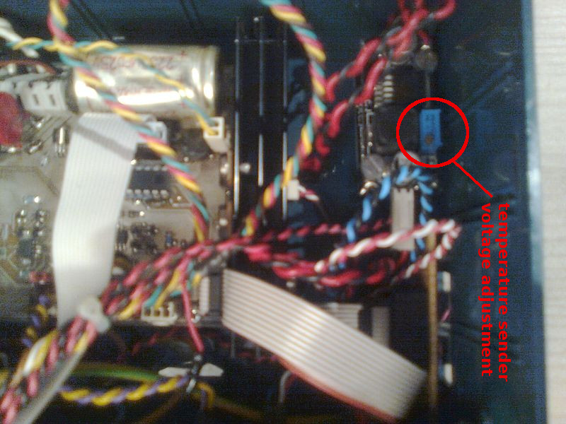
Instead of the forerun sensor temperature this menue shows the supply voltage of the temperature sender at bottom right. It shall be between 6.000V and 6.020V to ensure accuracy of the temperature conversion on the sender side. The prefix is V.
This voltage can be adjusted by a potentiometer inside the hc controller box, as shown in the following picture.
Please do not tune the potentiometer while the sender is connected to the hc-box.
Disconnect it first, then do the adjustment if necessary, and connect it again. Otherwise you endanger the sender electronic by too high voltages


When hc runs in default mode - the learning mode - the modes DENY and MEAS are interchanging. When a valid heating curve is available, the FOR mode is active and interchanges with the MEAS mode. The meaning of these modes is:
In hc internally, there are some more modes being processed. Actually, all of them go to the display but will almost never seen due to frequent changes, but the one or other could, so don't worry by then.

In this menue you use the up and down buttons to drive the mixer engine. The directions are:
You can drive only one direction at a time, the LEDs are signalling the active driving direction. Furthermore you need to switch off the engine before you can change the direction. This is done by either pressing the button of the same direction (while active) or pressing the button of the opposite direction. In both cases the engine is switched off first, if one direction is active. Afterwards, hc is prepared for a new choice of direction through the user.
During the activity of this menue, no controlling and measure cycles are executed, because they would confuse the user's manual drive intention.
So the display stands still and shows the values of the previous menue - don't care of them! Just the timer is still running.


The recent captured temperature values (I, O, F) are cyclically rotated. You can adjust the speed of rotation over the setup menue SMI -> show measurement interval. The browser can take 36 data sets which lead to a recording time of exactly 3 hours, because the measurement interval IV_MEAS occurs every 5 minutes. The browser runs reverse, thus the more recent data sets are shown first. If once the 3 hours rotation overflows, hc starts to overwrite from the tail, thus the oldest sets are replaced by recent ones.
These historical values are taken by hc when in learning mode (see insulation calculation). The user can take advantage of this for error diagnosis or measurement tests like "having a look how things behave".
In the following subsequent paragraphs all setup menue items available through hc are described. You go into the setup menue by holding down the up and down buttons simultaneously for at least 2 seconds, see also here.
The currently selected value is flashing every 500ms and can be changed by the up or down button. Values taking more than 8 bit of data size (>256) are changed by a delta of 10, those which are up to 8 bit are changed by 1. The illustrated values are the factory defaults, unless otherwise stated.

unit: [°C]
see also
This temperature is the leading value to wich hc tries to reach and hold the inner temperature, independent of the control mode.

unit: [°C]
see also
Offset value to the inner temperature measurement value. Physically the electronic of the temperature sender is very tight to the inner temperature sensor. The sender's anyhow low power consumption still can influence the value of the inner sensor due to the thermal emission of the electronic. This is why the OIT setup value comes into account. It enables the user to linearly compensate such a possible unwanted influence.

unit: [V]
To gain accurate measurement results, the ADC needs to be referenced as much close as possible to the operating voltage. This voltage is derived over a voltage regulator. Because of production tolerances each single regulator has its own specific output voltage.
The ARV setup value enables the user - well, it's more the vendor in that case - to readjust the reference voltage against these tolerances. The reason why it shall be necessary to readjust, could be a replacement of the regulator or a substantial change of the operating conditions.
Please do not change this value unless absolutely necessary. Otherwise you will receive inadequate temperature values and a confusion of controlling.

unit: [1/mA]
A value to define a constant current flow through a temperature sensor. Likely rather interesting to the vendor than to the user. The sensor current only changes when the hardware is modified or the operating conditions are changing substantially.
An adjustment of this value requires the measurement of the sensor current. That's why you are doing good to leave it as it is. In case of modification, the same consequences arise as for the ARV value, see above.

unit: [kΩ]
This resistance value is the sensor's resistance R0 @ 25°C in [kΩ]. It must be reconfigured, if a sensor with another R0 value is used.

unit: [s]
Defines the speed of browsing the historic temperature data sets when in menue No. 2. The unit is in seconds.

unit: [°C]
see also
When it is getting warmer outside, it comes to the point where the heater is not required anymore. For sure, this depends on the house's insulation grade. This setup value allows the adjustment of the shut down threshold. When the outer temperature exceeds this threshold, the system ist shut down. This means, the valve is getting totally closed.
There is an internal hysteresis of 0.4°C. When the outer temperature falls down for this difference, the system comes in action again. You can imitate the insulation grade of the house by a slightly higher or lower adjusted threshold.

unit: [min]
see also
The duration in minutes of driving the mixer engine in cw direction (closing the valve) when shutting down the system, see SDT. The value configured depends on the mixer engine's speed. It will rotate by a specific angle per time unit. Within this setup value you can come along to this.

unit: [1/10s]
see also
Enables the user to adjust the interval duration of the driving cycles to the mixer engine. The system's grade of reaction might be adapted to your needs via this setup value. When the system controls up or down, it rotates the mixer engine for the amount of time configured by this value. The unit is a tenth of a second, so the value of '3' means 300ms. The default value is 20, wich are 2s.

unit: [1]
see here for detailed description
The value you adjust here is a multiple of the measurement interval IV_MEAS in [min]. Thats why the unit is stated as [1].

unit: [1]
see here for detailed description
The value you adjust here is a multiple of the significant temperature change DELTA_TEMP in [°C ]. Thats why the unit is stated as [1].

unit: [1]
see here for detailed description
The value you adjust here is a multiple of the measurement interval IV_MEAS in [min]. Thats why the unit is stated as [1].
 1.8.6
1.8.6 
